 ×
×

Selecting the right ferrite core coil for your switching power supply design is one of the most critical decisions in power electronics engineering. The ferrite core coil directly influences efficiency, thermal performance, electromagnetic interference mitigation, and overall system reliability. Making an informed choice about ferrite core coil specifications can mean the difference between a design that operates smoothly for years and one that fails prematurely or generates excessive heat and noise.
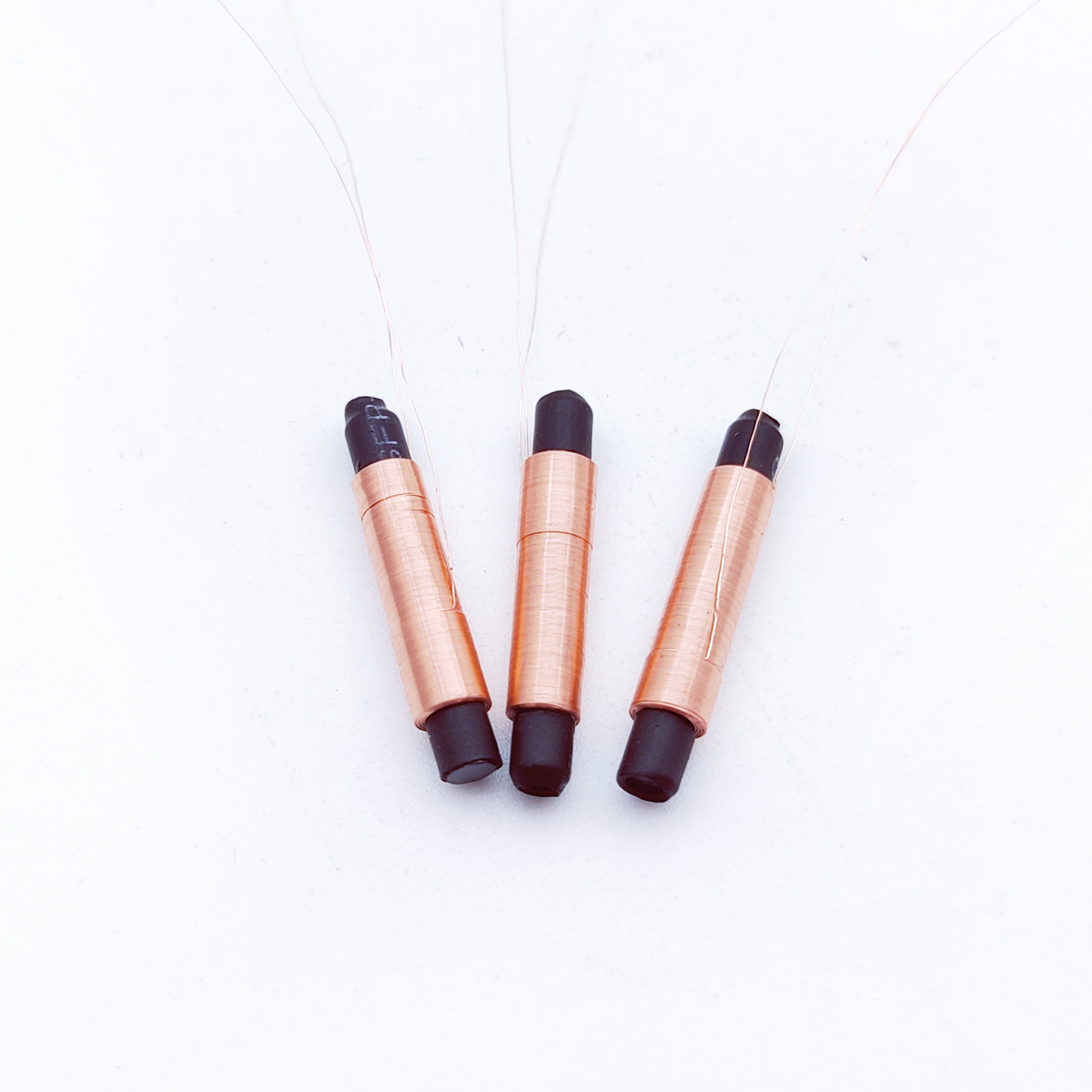
A ferrite core coil serves as the magnetic storage and energy transfer component in switching power supplies, buck converters, boost converters, and isolation transformers. The ferrite core coil must balance competing demands: minimizing core losses across the operating frequency range, handling the required current without saturation, fitting within physical constraints, and managing heat dissipation effectively. Understanding how to evaluate ferrite core coil options ensures your power supply design meets performance specifications while maintaining cost efficiency and reliability in production.
The ferrite core coil you select must use ferrite material matched to your operating frequency and power levels. Different ferrite formulations exhibit different saturation flux density, permeability, and loss characteristics across frequency ranges. A ferrite core coil operating at 100 kHz requires different material properties than one running at 500 kHz. The ferrite core coil's core loss increases dramatically at higher frequencies, so material selection directly impacts efficiency and thermal management in your switching power supply.
Soft ferrite materials used in ferrite core coil designs typically include manganese-zinc and nickel-zinc formulations. Each ferrite core coil material family has distinct advantages: manganese-zinc ferrite core coil compositions offer higher permeability and lower costs but higher losses at higher frequencies, while nickel-zinc formulations excel at higher frequencies with lower core losses but reduced permeability. Choosing the correct ferrite core coil material requires analyzing your specific switching frequency, power levels, and thermal constraints to optimize performance and efficiency.
Operating frequency is the primary driver of ferrite core coil core losses and heat generation. A ferrite core coil designed for 50 kHz switching cannot be directly substituted into a 500 kHz design without significant performance degradation and potential failure. The ferrite core coil's core loss doubles or triples with each frequency increase, making material selection critical. Low-frequency designs may use ferrite core coil materials with higher permeability for better inductance density, while high-frequency designs demand ferrite core coil materials optimized for low losses at the target switching frequency.
Temperature rise becomes more pronounced as switching frequency increases in a ferrite core coil. Your ferrite core coil operating at twice the frequency generates substantially more core heat even at identical power levels. This thermal stress accelerates material degradation and can shift the ferrite core coil's magnetic properties beyond acceptable tolerances. Proper ferrite core coil material selection ensures core losses remain within thermal budgets and temperature rise stays within acceptable limits across the entire operating range.
Inductance requirements drive the ferrite core coil's physical size and core geometry. Your switching power supply's inductance filter or converter requires a specific inductance value to achieve the desired current ripple, voltage regulation, and transient response. A ferrite core coil sized too small for the required inductance will saturate under normal operating conditions, causing core loss to spike dramatically and inductance to collapse. A ferrite core coil oversized for the inductance requirement wastes cost, space, and thermal performance unnecessarily.
Saturation flux density determines how much magnetic flux the ferrite core coil can handle before performance degrades. Your ferrite core coil must provide stable inductance across the entire current range without saturating. When a ferrite core coil saturates, permeability collapses, inductance drops, and core losses increase substantially. Calculating the peak magnetic flux density in your ferrite core coil accounting for DC bias, AC ripple current, and temperature effects ensures the core remains safely below saturation limits under worst-case operating conditions.
The ferrite core coil's wire gauge, winding configuration, and thermal dissipation capacity determine maximum sustainable current. Copper losses in the ferrite core coil windings plus core losses combine to generate heat that must dissipate to the environment. A ferrite core coil that overheats will eventually fail due to insulation breakdown, solder joint degradation, or core material demagnetization. Your ferrite core coil current rating must account for continuous operation at maximum ambient temperature with adequate margin for reliable field deployment.
Thermal management for a ferrite core coil requires careful attention to mounting, PCB copper area, and thermal vias if the ferrite core coil will operate continuously at high currents. Some applications benefit from adding a ferrite core coil heat sink or improving board-level thermal coupling. The ferrite core coil's temperature rise under full load determines reliability and expected lifetime. Properly evaluating thermal performance of your ferrite core coil design ensures consistent operation across the full temperature and load range without derating or accelerated aging.
Available board space often constrains ferrite core coil selection in compact switching power supply designs. Engineers must evaluate multiple ferrite core coil core geometries such as EE, EI, pot cores, and toroidal designs to find the best balance between inductance, current capacity, losses, and physical footprint. A ferrite core coil with toroidal geometry minimizes EMI coupling but requires more winding labor, while a ferrite core coil with EE geometry offers easier assembly and better thermal dissipation for the same inductance. The right ferrite core coil geometry depends on your specific space constraints, thermal requirements, and cost targets.
Physical size of the ferrite core coil directly correlates with inductance density and current capacity. A larger ferrite core coil can generally achieve lower losses and better heat dissipation for the same inductance specification. A smaller ferrite core coil saves space but may require compromises in loss, temperature rise, or cost if insufficient core material exists to meet all requirements efficiently. Evaluating multiple ferrite core coil sizes and geometries during design ensures you find the optimal solution that meets all constraints without over-engineering.
Quality ferrite core coil suppliers provide detailed performance data including core loss curves across temperature ranges, permeability tolerance specifications, and saturation characteristics. A reliable ferrite core coil supplier publishes loss curves at your exact operating frequency, not just generic data. The ferrite core coil supplier's specifications should allow you to calculate expected core losses at your actual switching frequency and peak flux density. Vague ferrite core coil datasheets without frequency-specific loss data make accurate design impossible and often result in over-sized, inefficient designs or field failures.
Working with an established ferrite core coil supplier ensures consistent material properties and quality across production batches. A ferrite core coil sourced from an inconsistent supplier may exhibit unacceptable variation in core loss, permeability, or saturation characteristics, causing performance drift across your product line. Quality ferrite core coil suppliers maintain traceability, provide certificates of analysis, and offer technical support for design optimization. Evaluating supplier quality and data transparency is as important as evaluating the physical specifications of the ferrite core coil itself.
The most influential factors in ferrite core coil selection are operating switching frequency, required inductance value, maximum current, available space, and thermal constraints. Your ferrite core coil material must match the frequency range to minimize core losses and heat generation. The ferrite core coil's saturation characteristics must accommodate peak currents without degradation. Available PCB area constrains ferrite core coil size and geometry options. Thermal budget determines whether your ferrite core coil can operate reliably without derating or excessive temperature rise during continuous operation.
Core loss calculation for a ferrite core coil requires manufacturer loss curves specific to your operating frequency, peak flux density, and core material. Most ferrite core coil suppliers publish loss density curves in milliwatts per cubic centimeter at specified frequencies and temperatures. Multiply loss density by the ferrite core coil's core volume to get total core loss in watts. Account for temperature coefficient effects on loss since a ferrite core coil running hot experiences higher losses than the same core at room temperature, creating a feedback loop that requires careful thermal management consideration.
A ferrite core coil optimized for one frequency generally performs poorly when used at significantly different frequencies. A ferrite core coil material chosen for 100 kHz operation will exhibit excessive core losses and temperature rise at 500 kHz operation. The inductance value and saturation characteristics designed for one application may not match another application's requirements. While ferrite core coil core geometry remains the same, the material properties and loss characteristics are frequency-dependent, making substitution without re-evaluation risky and potentially unreliable in production environments.
 Hot News
2026-10-15
2026-10-13
2026-10-08
2026-10-06
2026-10-01
2026-09-21
Zhongshan Landa Technology: ISO9001 & UL-certified manufacturer of custom electromagnets, push-pull solenoids, and induction coils for automation, medical, auto & appliances. Trusted global partner since 2008.
3F, Building 4, No.8 North Industrial Avenue Xiaolan, Xiaolan Town, Zhongshan, Guangdong, China
Copyright © Zhongshan Landa Technology Co., Ltd All Rights Reserved Privacy Policy

 EN
EN