EN




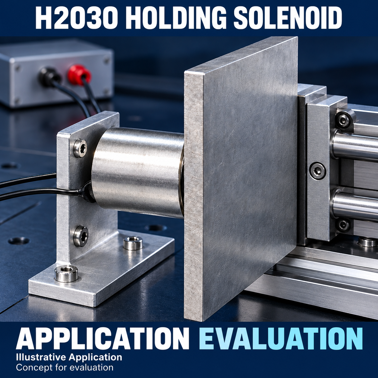
H2030 Round Holding Electromagnet, 20 × 30 mm, 12V/24V DC
Compact cylindrical holding solenoid with rear M5 mounting and 200 mm leads
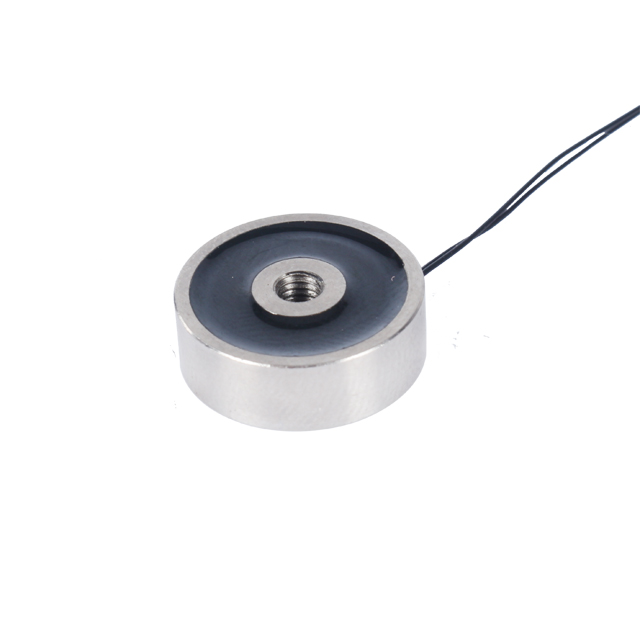
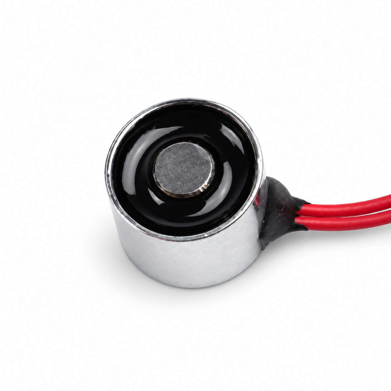
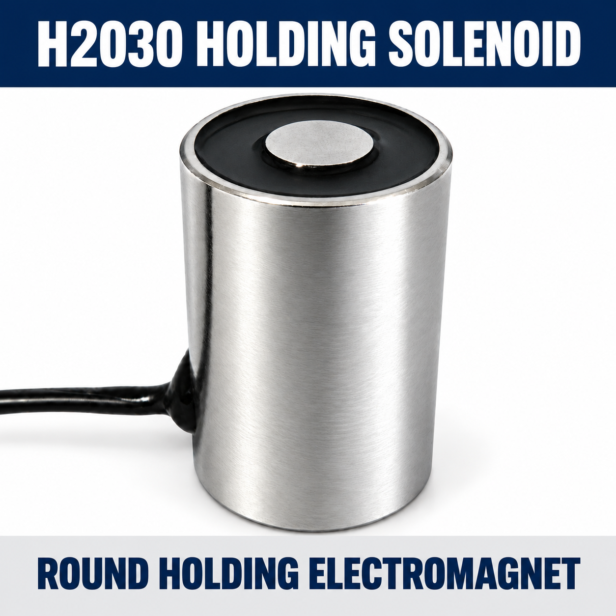
The Landa H2030 is a round holding electromagnet with a 20 mm diameter and 30 mm body length. H2030-12A60 and H2030-24A240 are separate coil versions. The rear M5 interface and 200 mm leads support integration review for compact holding assemblies. Confirm duty cycle, full-face workpiece contact and the approved electrical specification before selection.
- Overview
- Recommended Products
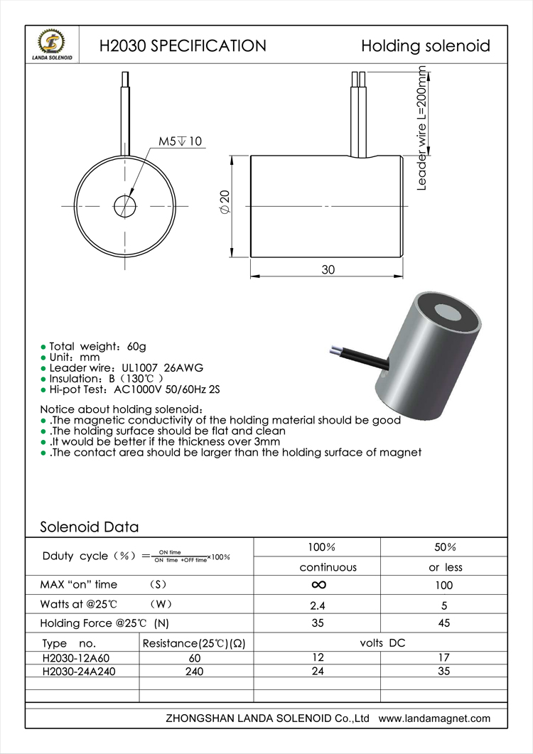
- Cylindrical body: Ø20 × 30 mm.
- Listed product mass: 60 g.
- Rear M5 mounting hole with a 10 mm depth callout.
- UL1007 26AWG lead wire, nominally 200 mm long.
- Separate H2030-12A60 and H2030-24A240 coil versions.
- Source table distinguishes continuous duty from intermittent operation.
- Identify the coil. Select the exact model and obtain the approved voltage, duty cycle and thermal conditions before powering the unit. Do not apply unconfirmed 17V or 35V entries.
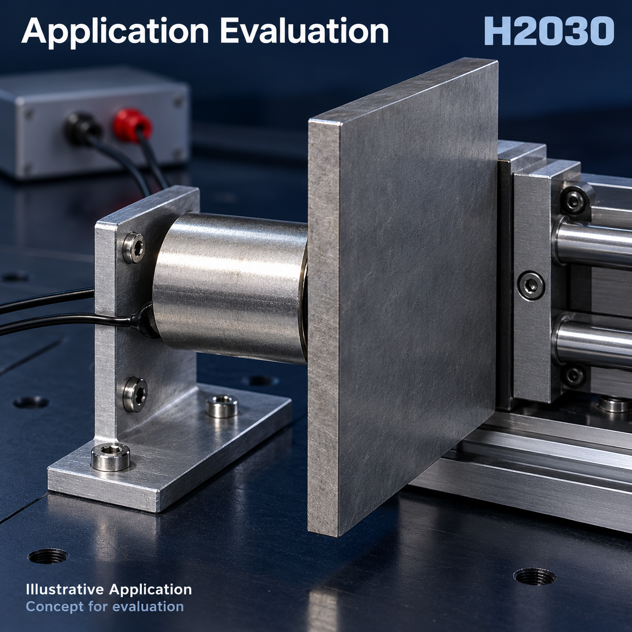
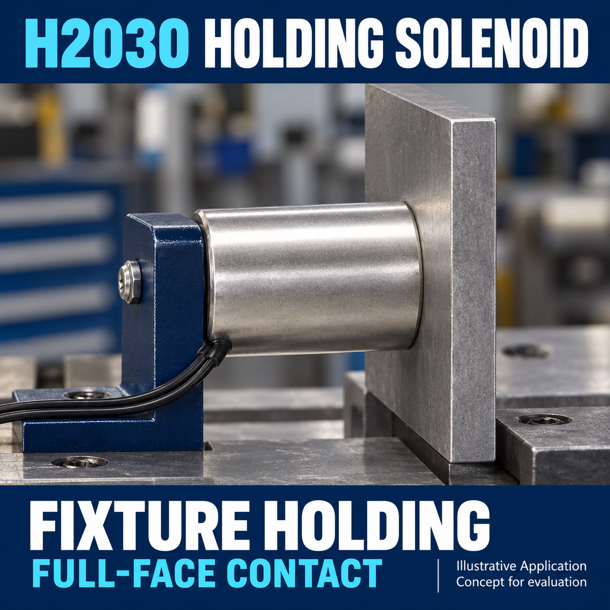
- Cover the complete pole face. The effective flat armature contact face must be at least as large as the entire Ø20 mm holding face, including the outer annular pole and central pole. A rectangular contact face must encompass the complete circular face in both directions. Do not use a narrow strip, plate edge, corner or center-only pad.
- Prepare the workpiece. Use a clean, flat ferromagnetic contact surface with good magnetic permeability. The source recommends thickness greater than 3 mm and contact area larger than the holding face; confirm the actual material and thickness for your design.
- Control gaps and alignment. Keep the armature centered, parallel and flush in the holding state. Coatings, roughness, debris and misalignment introduce air gaps and may reduce force. In a release mechanism, verify the closing path can restore full-face contact.
- Verify rear mounting. Use the documented M5 interface. Confirm engagement and torque; the 10 mm drawing callout is not an approved screw length.
- Validate temperature and timing. Confirm ambient temperature, mounting heat dissipation and cycling. Insulation-class temperature is not an ambient operating rating. Never treat the intermittent row as continuous capability.
- Check controls and release. Review the driver and inductive-load suppression for the application, then test release with the actual workpiece and mechanism.
ROUND HOLDING ELECTROMAGNET
H2030 Round Holding Electromagnet, 20 × 30 mm, 12V/24V DC
Compact cylindrical holding solenoid with rear M5 mounting and 200 mm leads
Product Overview
The Landa H2030 is a round holding electromagnet with a 20 mm diameter and 30 mm body length. The series specification lists H2030-12A60 and H2030-24A240 as separate coil versions. A rear M5 mounting interface and 200 mm leads provide the documented starting points for mechanical integration.
The supplied documents describe an energized holding solenoid, rather than a permanent power-off holding magnet. Selection requires an approved electrical specification, full-face contact with a suitable ferromagnetic workpiece and review of the duty cycle and thermal conditions.
Key Features
Technical Specifications
| Item | Documented value / qualification |
|---|---|
| Product family | H2030 round holding electromagnet / holding solenoid |
| Body diameter × length | 20 × 30 mm |
| Listed mass | 60g |
| Rear mounting | M5; depth callout 10 mm. Confirm usable engagement, screw specification and torque. |
| Lead wire | UL1007 26AWG; nominal 200 mm. Black on the 24V drawing. Length tolerance not supplied. |
| H2030-12A60 | 12V DC entry; 60 Ω at 25°C. Resistance tolerance not supplied. |
| H2030-24A240 | 24V DC entry; 240 Ω at 25°C. Drawing specifies ±10% resistance tolerance. |
| Insulation / dielectric rating | Source conflict; pending engineering approval. |
| Certification / IP rating | Not established by the supplied evidence. |
Electrical Performance
Source data for engineering review. The series specification lists the following values at 25°C. Complete force-test conditions and the meaning of this temperature require confirmation.
| Listed duty | Power at 25°C | Holding force at 25°C | Maximum on-time |
|---|---|---|---|
| 100% continuous | 2.4 W | 35 N | Continuous symbol in source; actual thermal installation limits require approval. |
| 50% or less | 5 W | 45 N | 100 seconds; cycle and cooling conditions require confirmation. |
The specification also contains 17V and 35V entries. Their approved operating conditions require engineering confirmation; they are not supply recommendations. The 45 N intermittent value must not be presented as continuous-duty performance.
The 24V drawing separately states F ≥ 3.5 “Kg” at a 0 mm gap and 24V DC. Clarify the force unit and acceptance criterion before equating this entry with the series table. No verified force-versus-gap or temperature-rise curve has been supplied.
Working Principle
Electrical current in the coil produces a magnetic field at the holding face. A suitable ferromagnetic armature closes the magnetic path across the pole face. The documented H2030 is an energized holding design; it is not specified as a permanent power-off holding product.
On removal of coil power, the energized field decays. Actual release depends on residual attraction, the workpiece and the control circuit. The 24V drawing includes a reference residual-magnetism entry without a complete method; zero residual force and a specific release time are not established.
Application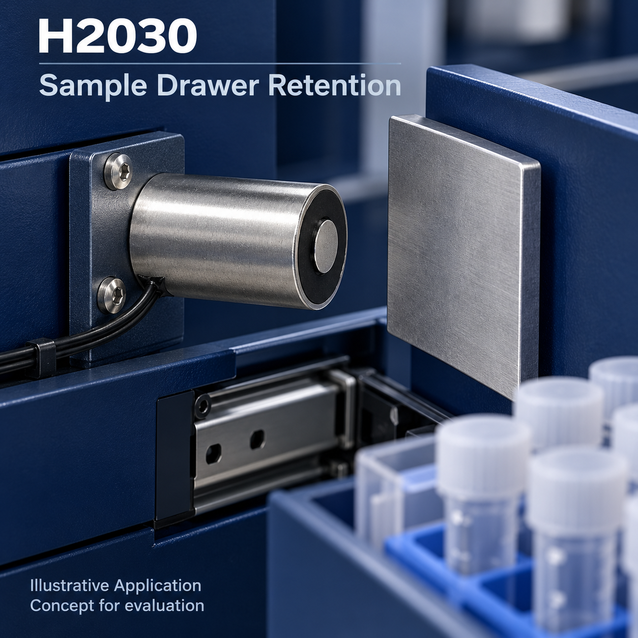
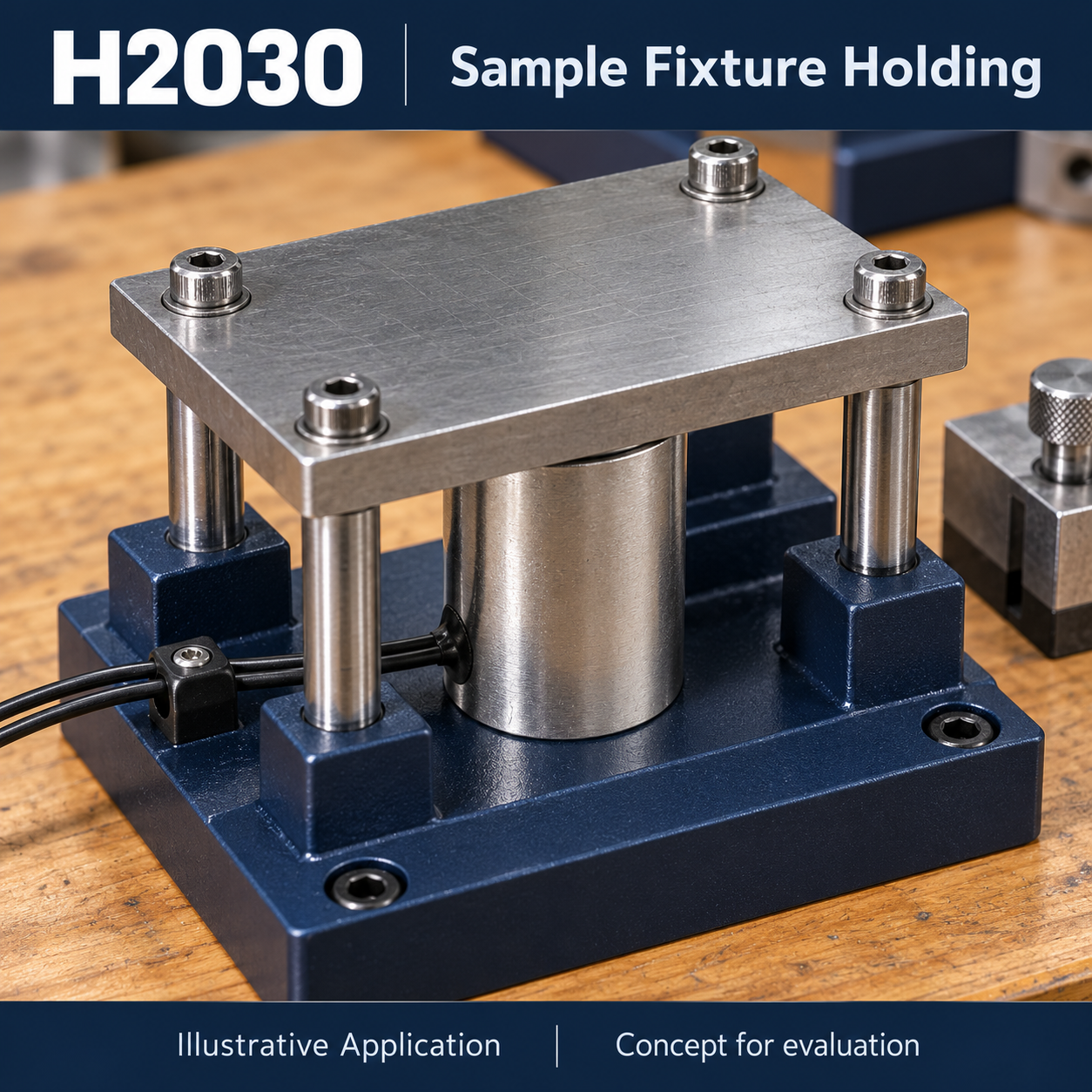
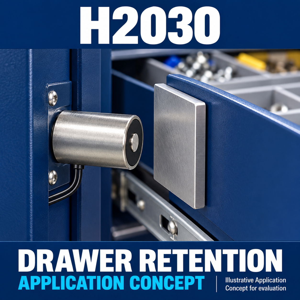
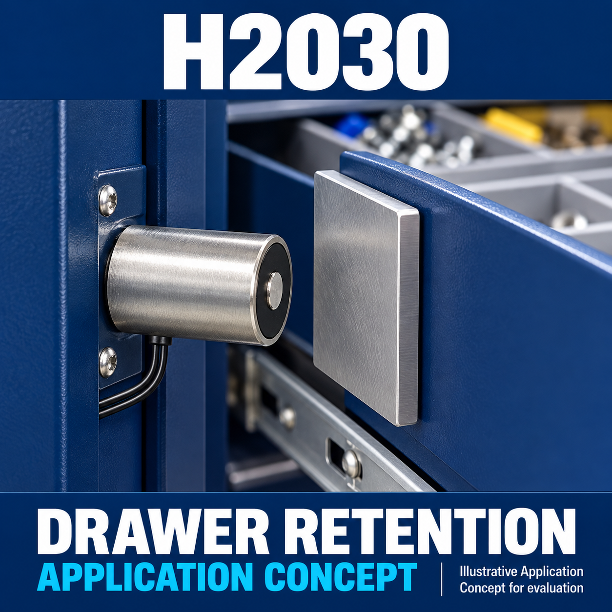
The H2030 may be evaluated for supported steel-carrier retention, compact inspection-panel retention, sample fixtures and material-guide assemblies. These are potential design concepts, not verified customer installations or approved safety applications.
Evaluate the actual holding margin, release behavior and failure mode before selecting the product. The source holding-force values are not rated lifting capacities.
Installation & Selection Guide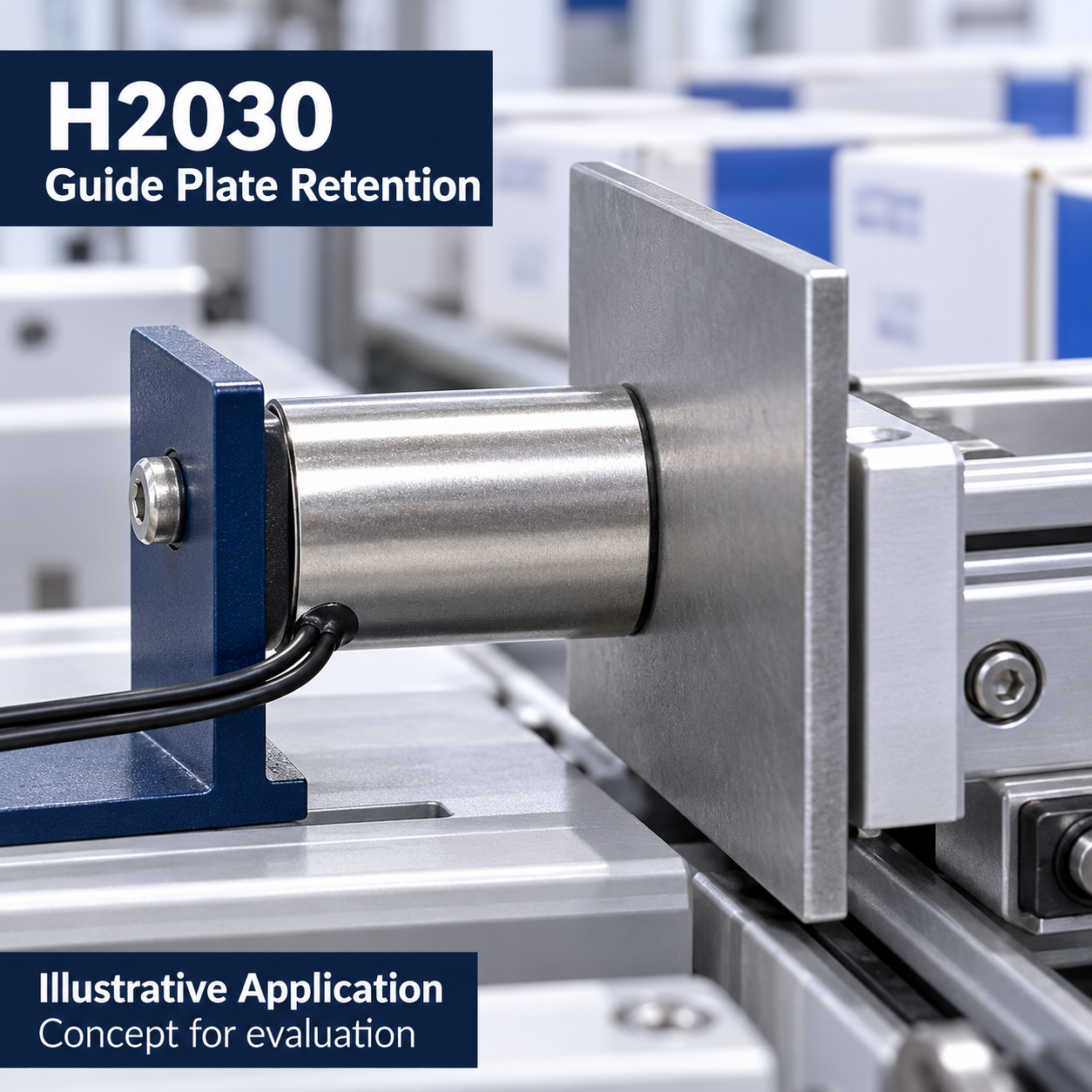
FAQ
Does one H2030 coil accept both 12V and 24V?
No. The specification lists H2030-12A60 and H2030-24A240 as separate versions. Confirm the approved supply for the selected version.
Can 45 N be used as a continuous holding rating?
No. The series table assigns 45 N to 50% duty or less, with maximum on-time of 100 seconds. The continuous row lists 35 N. Both require complete test and thermal conditions.
Can I use 17V or 35V?
Do not use these entries as operating instructions until engineering confirms their permitted conditions.
How large must the armature contact face be?
It must cover the entire Ø20 mm holding face, including both the outer and central poles. Overall workpiece area alone is insufficient if the actual contact is a narrow edge or small pad. The source recommends a contact area larger than the magnet face.
Why can actual holding force differ?
Air gap, material, thickness, contact area, surface condition and temperature affect performance. Full-face coverage alone does not prove the listed force will be achieved.
Does UL1007 wire prove product certification?
No. The wire designation does not establish certification of the complete electromagnet.
Does power removal guarantee immediate release?
A release time and zero residual attraction are not established. Test the actual workpiece, driver and mechanism.
OEM Customization
Submit your required supply, duty cycle, mounting, wiring, workpiece and environmental conditions for engineering review. Feasibility, available options, approved drawings, certification scope and commercial terms must be confirmed in the quotation. No unverified customization capability is implied.
Request a Quote
Provide the required coil model, quantity, supply voltage, on/off timing, required holding force, air gap, workpiece material and thickness, effective contact-face size, ambient temperature and mounting arrangement. Include release requirements and request the approved specification and sample evaluation before final selection.