 ×
×

When engineers decide to downsize a holding or actuation device, the mini electromagnet immediately enters the conversation. These compact components promise space savings and reduced weight, but they also introduce real performance compromises that every designer must understand before committing to a smaller form factor. Choosing a mini electromagnet without mapping those trade-offs first can lead to underperforming systems, premature field failures, or costly redesigns.
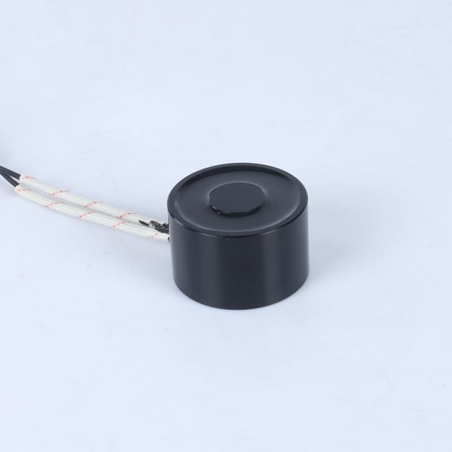
The core challenge with any mini electromagnet is physics: magnetic force scales with coil volume and core cross-section, so shrinking the device inevitably reduces the raw holding capacity. Understanding exactly where force is lost, how thermal behavior changes, and what design strategies can recover some performance is essential for any engineer or product developer evaluating a mini electromagnet for a real-world application.
A mini electromagnet generates its holding force through the magnetic flux concentrated in its iron or steel core. When the core diameter shrinks, the effective pole face area decreases, and the total flux the mini electromagnet can channel drops accordingly. Because holding force is proportional to the square of flux density and pole area, even a modest reduction in dimensions produces a disproportionately large drop in usable force. This non-linear relationship is the most critical trade-off designers face when they choose a mini electromagnet over a full-size unit.
A mini electromagnet with half the diameter of a standard unit does not deliver half the force — it may deliver only one-quarter or less, depending on the geometry and the gap between the magnet face and the target surface. This reality means that specifying a mini electromagnet requires a careful force budget, not simply a dimensional substitution.
The coil wound around the core of a mini electromagnet determines how many ampere-turns the device can generate. A smaller form factor means fewer turns of wire and a lower current capacity before resistive heating becomes problematic. Every mini electromagnet has a duty-cycle ceiling driven by this thermal limit. Pushing a mini electromagnet beyond its rated duty cycle causes coil temperature to rise rapidly, which increases winding resistance, reduces current flow, and ultimately degrades holding force further. Designers must therefore treat the duty-cycle specification of a mini electromagnet as a hard operating boundary rather than a guideline.
Thermal management is where the mini electromagnet faces its most demanding engineering constraint. A full-size electromagnet spreads resistive heat across a large surface area, allowing passive air cooling to maintain safe operating temperatures. A mini electromagnet compresses that same power dissipation challenge into a fraction of the volume. The surface-area-to-volume ratio of a mini electromagnet is lower relative to its heat generation per unit volume, meaning it heats faster and needs more careful thermal design. Mounting a mini electromagnet against a thermally conductive chassis, using thermally rated potting compounds, or selecting a lower duty cycle are practical strategies that help manage this issue.
Most compact designs operate a mini electromagnet on 12 V or 24 V DC, which suits lightweight driver circuits and standard industrial control hardware. Running a mini electromagnet at its rated voltage ensures predictable coil current and consistent force output. Over-voltage driving to boost force in a mini electromagnet is technically possible for very short duty cycles, but it accelerates insulation degradation and shortens service life considerably. A better approach is to select a mini electromagnet whose rated holding force genuinely matches the application load, rather than attempting to extract extra performance through electrical overloading.
Some engineers use a peak-and-hold drive strategy with a mini electromagnet: a higher voltage pulse energizes the coil quickly to build flux, then a lower holding voltage sustains the magnetic circuit at reduced power. This technique extracts better response time from a mini electromagnet without the sustained thermal stress of continuous high-voltage operation. It is particularly useful in automated assembly, robotics, and vending equipment where the mini electromagnet must cycle rapidly under tight energy budgets.
Holding force ratings for a mini electromagnet are always measured under ideal conditions: clean flat mating surfaces, zero air gap, and rated voltage applied. Real installations rarely achieve all three simultaneously. Surface roughness, paint, coating, or slight misalignment introduces an effective air gap that can reduce the force of a mini electromagnet by 30 to 60 percent versus the rated value. Specifying a mini electromagnet with a meaningful force margin above the actual required load is therefore standard engineering practice, not conservative over-engineering.
For example, a mini electromagnet rated at 200 N of holding force provides a practical working load well below that figure in typical installations. Selecting such a device for a 60 to 80 N application leaves adequate margin for surface conditions, voltage variation, and temperature effects, all of which reduce actual output from the mini electromagnet in service.
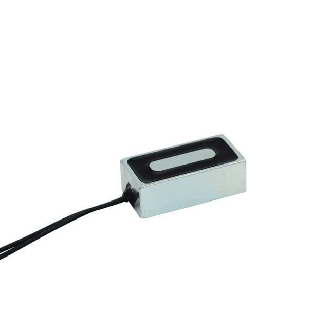
The round pot-magnet form factor is the most common geometry for a mini electromagnet because it maximizes pole face area per unit volume and concentrates flux efficiently. Flat mounting flanges, threaded bodies, and recessed faces are all available configurations that affect how a mini electromagnet integrates into a product. Engineers should also consider the stroke distance in latching applications, because a mini electromagnet loses force rapidly as the air gap opens — far more so than a larger device with a deeper magnetic circuit. Understanding this steep force-distance curve is critical for applications where the mini electromagnet must attract a target from more than a fraction of a millimeter away.
A mini electromagnet has a shallow magnetic circuit, so the reluctance of even a tiny air gap represents a large fraction of the total magnetic path. This causes flux — and therefore holding force — to drop sharply as gap distance increases. Larger electromagnets have deeper cores that tolerate air gaps more gracefully, but a mini electromagnet must be mounted with very close, flat contact to achieve its rated holding force.
Yes, but only if the mini electromagnet is rated for continuous duty and the installation provides adequate heat dissipation. Many compact units are rated for intermittent or limited-duty cycles. Running a mini electromagnet continuously beyond its thermal rating will cause coil temperature to exceed safe limits, degrade insulation, and reduce holding force. Always verify the duty cycle specification and ensure the mounting arrangement conducts heat away from the mini electromagnet body effectively.
The most effective strategies are ensuring perfect mating surface contact, minimizing air gap through precise mechanical design, using a peak-and-hold drive circuit to maximize initial flux, and selecting a mini electromagnet with the highest coil fill factor available for its size class. Material choice also matters: a mini electromagnet wound with high-conductivity copper and built around a high-permeability low-carbon steel core will outperform a lower-grade equivalent at the same dimensions.
 Hot News
2026-10-15
2026-10-13
2026-10-08
2026-10-06
2026-10-01
2026-09-21
Zhongshan Landa Technology: ISO9001 & UL-certified manufacturer of custom electromagnets, push-pull solenoids, and induction coils for automation, medical, auto & appliances. Trusted global partner since 2008.
3F, Building 4, No.8 North Industrial Avenue Xiaolan, Xiaolan Town, Zhongshan, Guangdong, China
Copyright © Zhongshan Landa Technology Co., Ltd All Rights Reserved Privacy Policy

 EN
EN