 ×
×

The physical structure of a bobbin coil determines its electromagnetic performance in ways that engineers must understand to optimize circuit efficiency and reliability. Bobbin coil geometry encompasses wire diameter, winding density, core material selection, and overall dimensional parameters that collectively influence how the coil stores and releases magnetic energy. When designing inductors, transformers, or electromagnetic actuators, the relationship between bobbin coil dimensions and both inductance value and quality factor becomes critical to achieving desired electrical characteristics. Understanding this relationship allows engineers to make informed design choices that balance performance requirements with manufacturing constraints and cost considerations.
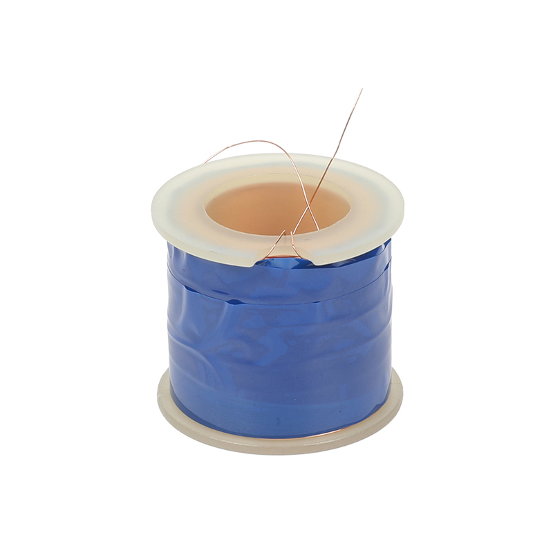
Inductance and quality factor are interdependent metrics that reflect how efficiently a bobbin coil performs within a circuit. Inductance measures the coil's ability to store energy in its magnetic field, while the Q factor (quality factor) represents the ratio of energy stored to energy dissipated, indicating overall efficiency. The bobbin coil geometry directly controls both metrics through mechanisms involving wire cross-sectional area, coil pitch, turn count, and the spacing between conductors. Engineers who master these geometric relationships can design coils that meet strict performance specifications while minimizing weight, volume, and material costs in power supplies, wireless charging systems, and industrial control applications.
The wire diameter used in a bobbin coil directly affects both the inductance value and the coil's resistance characteristics. Thicker wire conductors reduce ohmic losses, which improves the Q factor by decreasing the dissipated power relative to stored energy. However, thicker wire also reduces the number of turns that can fit within a fixed bobbin coil space, which lowers the total inductance unless the core is enlarged. This creates a design trade-off where engineers must balance wire gauge selection against available winding area and target inductance values. The bobbin coil winding area constrains how much conductor material can physically fit, making wire diameter one of the most influential geometric parameters in inductance optimization.
Inductance increases proportionally with the square of the turn count in a bobbin coil, a relationship described by Faraday's law of electromagnetic induction. Higher turn counts require either thinner wire, tighter winding density, or larger bobbin coil dimensions to accommodate all conductors. The bobbin coil geometry constrains maximum winding density, which is limited by insulation thickness, manufacturing precision, and thermal considerations. Packing more turns into a bobbin coil increases inductance but also increases total wire length and resistance, which can degrade the Q factor if the resistance gain exceeds the inductance benefit. Optimal bobbin coil design finds the density point where inductance reaches the target value while Q factor remains acceptable for the intended application.
The Q factor of a bobbin coil is fundamentally limited by the resistance of the wire used in winding. Resistance increases with wire length and decreases with conductor cross-sectional area, both of which are influenced by bobbin coil geometry. A bobbin coil with a larger diameter requires longer wire for each turn, increasing total resistance and lowering Q factor unless wire gauge is increased compensatively. Conversely, a bobbin coil with a smaller diameter and higher turns per unit length might achieve better Q factor if the wire can remain thick enough to minimize resistive losses. The bobbin coil geometry must be optimized so that the wire path length and cross-sectional area balance to produce the lowest possible resistance for the target inductance value.
The core material inserted into a bobbin coil fundamentally affects how inductance and Q factor scale with geometric parameters. Air-core bobbin coil designs rely entirely on the magnetic field in free space, making inductance dependent on geometry alone without core losses. Ferrite or iron powder cores inserted into a bobbin coil increase inductance but introduce core losses that reduce Q factor, especially at higher frequencies. The bobbin coil geometry must accommodate the core while maintaining sufficient space for wire winding and cooling. A properly sized bobbin coil allows the core to be inserted without excessive gaps, ensuring maximum coupling between the core and the magnetic field. The selection of core material and core size within the bobbin coil geometry directly determines whether inductance gains from core insertion outweigh Q factor losses from core losses.
The bobbin coil geometry must account for heat dissipation, as resistive losses in the wire generate heat that can degrade wire insulation and reduce circuit reliability. A bobbin coil with tightly packed windings offers high inductance per unit volume but impedes heat flow, potentially causing thermal failure in high-current applications. Conversely, a bobbin coil with looser winding density allows better air circulation and heat dissipation but requires more physical space or thinner wire to maintain the same inductance. Industrial applications often require bobbin coil designs that balance inductance density with thermal management, sometimes using larger bobbins or rectangular cross-sections to provide better cooling paths. Engineers must verify that the bobbin coil geometry selected for a given application can safely dissipate the expected power losses without exceeding maximum insulation temperatures.
At high frequencies, skin effect causes AC current to concentrate near the surface of the wire conductor, effectively reducing the usable cross-sectional area and increasing AC resistance. The bobbin coil geometry must be adjusted for the operating frequency to minimize skin effect losses. For high-frequency applications, a bobbin coil may use multiple thinner wire strands in parallel instead of a single thick conductor, a configuration that increases effective surface area and reduces skin effect resistance. Litz wire, which consists of many small strands twisted together, is often used in bobbin coil windings for radio frequency and switching power supply applications. The bobbin coil geometry and wire selection must work together to maintain acceptable Q factor across the intended frequency range, which requires careful engineering analysis and sometimes experimental validation.
The bobbin coil geometry must be specified with manufacturing tolerances tight enough to ensure consistent inductance and Q factor performance across production batches. Wire diameter variation, bobbin coil dimensional tolerance, and winding tension all affect the final inductance value and quality factor. A bobbin coil design that is sensitive to small geometric variations will produce inconsistent performance and lead to higher scrap rates and customer returns. Robust bobbin coil geometry designs incorporate manufacturing margins and specify tolerances that are achievable with standard industrial equipment. Quality control processes must measure key bobbin coil dimensions and verify inductance and Q factor on sample units to detect production drift before large batches become defective.
Inductance increases with the square of the turn count in a bobbin coil. Doubling the turns quadruples the inductance, assuming all other geometric parameters remain constant. However, adding more turns requires either thinner wire or larger bobbin coil dimensions, both of which introduce trade-offs. Thinner wire increases resistance, reducing Q factor, while larger bobbin coil sizes increase cost and volume. The relationship between turns and inductance is predictable using inductance formulas, but engineers must optimize the bobbin coil geometry to avoid unintended negative effects on overall circuit performance.
Thicker wire diameter reduces DC and AC resistance in a bobbin coil, directly improving the Q factor by decreasing energy losses. A bobbin coil wound with thicker wire dissipates less power as heat and returns more of the stored magnetic energy efficiently to the circuit. However, thicker wire occupies more space on the bobbin coil, limiting the number of turns that can fit in a fixed space, which reduces inductance. Engineers must select wire diameter carefully to balance resistance reduction against inductance requirements, sometimes adjusting bobbin coil dimensions to accommodate thicker wire if Q factor improvement is critical to application success.
An air-core bobbin coil typically exhibits higher Q factor than a comparable ferrite-core bobbin coil because ferrite cores introduce core losses that increase energy dissipation. However, ferrite-core bobbin coil designs achieve much higher inductance for the same physical size, making them necessary for many space-constrained applications. An air-core bobbin coil requires more turns or larger dimensions to reach the same inductance, which increases wire length and resistance. The choice between air-core and ferrite-core bobbin coil designs depends on whether Q factor efficiency or inductance density is the priority for the intended application and frequency range.
 Hot News
2026-10-15
2026-10-13
2026-10-08
2026-10-06
2026-10-01
2026-09-21
Zhongshan Landa Technology: ISO9001 & UL-certified manufacturer of custom electromagnets, push-pull solenoids, and induction coils for automation, medical, auto & appliances. Trusted global partner since 2008.
3F, Building 4, No.8 North Industrial Avenue Xiaolan, Xiaolan Town, Zhongshan, Guangdong, China
Copyright © Zhongshan Landa Technology Co., Ltd All Rights Reserved Privacy Policy

 EN
EN