 ×
×

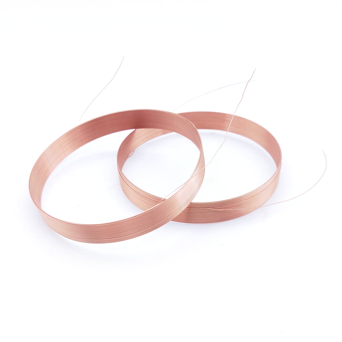
When designing advanced PCB assemblies and precision sensors, the choice of inductive components directly impacts performance, efficiency, and reliability. Among various coil architectures, the air core coil stands out as a preferred solution for applications demanding minimal magnetic losses, high-frequency stability, and predictable electromagnetic behavior. Unlike iron core or ferrite core alternatives, an air core coil eliminates core saturation risks and hysteresis losses, making it particularly suitable for RF circuits, resonant tank designs, and sensitive measurement instruments.
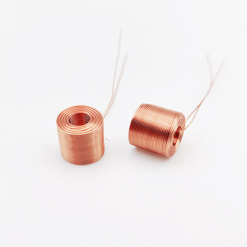
Understanding why an air core coil delivers measurable advantages in PCB and sensor contexts requires examining its fundamental operating principles, thermal characteristics, and real-world application scenarios. This article explores the technical and practical reasons that make an air core coil the optimal choice for modern electronic design challenges, from impedance matching networks to non-contact sensing systems.
One of the most compelling reasons to choose an air core coil is the complete absence of magnetic core saturation. Traditional inductors with ferrite or iron cores exhibit non-linear behavior at high current levels, where the core material reaches its magnetic flux density limit. An air core coil bypasses this limitation entirely because air has a constant relative permeability of approximately 1.0 across all operating conditions. This linearity ensures that inductance remains stable regardless of current amplitude, preventing distortion in signal processing applications.
Hysteresis losses, which occur when magnetic domains in ferromagnetic cores repeatedly realign during AC operation, represent another source of inefficiency that an air core coil eliminates. These losses manifest as heat generation and energy dissipation, reducing overall circuit efficiency. By using an air core coil design, engineers avoid hysteresis entirely, which proves critical in battery-powered devices and precision measurement systems where every milliwatt of power loss matters. The air core coil maintains consistent performance without the energy penalties associated with core materials.
The air core coil architecture excels in high-frequency applications because it avoids the frequency-dependent losses inherent in magnetic core materials. Ferrite cores exhibit increased losses at elevated frequencies due to eddy currents and residual core losses, which degrade the quality factor Q of the inductor. An air core coil demonstrates exceptional Q factors at radio frequencies, often exceeding values of 200 to 400 in well-designed implementations, compared to 50 to 100 for typical ferrite core inductors operating in the same frequency range.
This superior Q factor translates directly into sharper resonance characteristics in tuned circuits, reduced insertion loss in filters, and improved selectivity in RF front-end designs. For PCB designers working with wireless communication modules, antenna matching networks, or software-defined radio systems, the air core coil provides predictable impedance characteristics that remain stable across temperature variations and manufacturing tolerances. The air core coil enables tighter bandwidth control in resonant circuits, which is essential for meeting stringent regulatory requirements in spectrum-constrained environments.
Temperature coefficient performance represents another area where the air core coil demonstrates clear superiority. Magnetic core materials exhibit temperature-dependent permeability changes, causing inductance drift as operating temperature varies. An air core coil shows minimal inductance variation with temperature, typically limited to the thermal expansion coefficient of the conductor material itself, which ranges from 10 to 30 parts per million per degree Celsius for common copper wire.
This thermal stability makes the air core coil ideal for precision sensor applications where measurement accuracy depends on stable component values. In industrial sensors operating across wide temperature ranges from minus 40 to plus 125 degrees Celsius, an air core coil maintains consistent performance without requiring temperature compensation circuits. The absence of core material also eliminates Curie temperature concerns, where ferromagnetic materials lose magnetic properties above specific temperature thresholds. The air core coil operates reliably in high-temperature environments where ferrite-based alternatives would fail.
Modern PCB design prioritizes component miniaturization and automated assembly compatibility. The air core coil architecture adapts naturally to surface-mount technology through planar spiral configurations or vertical solenoid structures that integrate directly onto PCB substrates. These air core coil implementations can be fabricated using standard PCB copper traces, eliminating discrete component sourcing and simplifying supply chain management.
Planar air core coil designs embedded within PCB layers offer exceptional space efficiency for applications such as RFID antennas, wireless power transfer receivers, and inductive proximity sensors. By incorporating an air core coil directly into the PCB stackup, designers reduce assembly costs, improve reliability by eliminating solder joint failures, and achieve precise geometric control that would be impossible with discrete wound components. The air core coil approach enables complex multi-layer configurations that optimize electromagnetic coupling while maintaining compact footprints.
In sensor applications, the air core coil delivers exceptional linearity across wide dynamic ranges. Inductive sensors using air core coil sensing elements maintain proportional output over large displacement or proximity variations without the sudden non-linearity that occurs when core materials approach saturation. This characteristic is particularly valuable in position sensors, eddy current testing equipment, and metal detection systems where measurement accuracy depends on linear electromagnetic field response.
The air core coil also enables bidirectional sensing without hysteresis-induced measurement errors. In applications such as linear variable differential transformers LVDTs or rotary variable differential transformers RVDTs, an air core coil architecture ensures that forward and reverse motion produce identical electrical responses, eliminating backlash errors in precision positioning systems. The air core coil provides repeatable measurements without the drift and aging effects associated with magnetic core materials, which can change properties over time due to mechanical stress or thermal cycling.
The air core coil contributes to improved electromagnetic compatibility EMC performance in sensitive electronic systems. Without magnetic core materials that can introduce non-linear harmonics or unpredictable coupling effects, an air core coil generates cleaner electromagnetic fields with minimal spurious frequency content. This characteristic simplifies EMC compliance testing and reduces the need for extensive shielding in mixed-signal PCB designs.
For medical devices, aerospace systems, and automotive electronics where electromagnetic interference standards are stringent, the air core coil offers a lower-risk design approach. The predictable field distribution of an air core coil allows accurate electromagnetic simulation during the design phase, reducing costly redesign iterations. The air core coil also exhibits lower coupling to adjacent traces and components compared to ferrite core alternatives, which can create localized field concentrations that cause crosstalk in densely populated PCB layouts.
Designing an effective air core coil requires understanding the relationship between physical geometry and electrical performance. The inductance of an air core coil depends primarily on the number of turns, coil diameter, coil length, and turn spacing. For a single-layer solenoid air core coil, inductance can be approximated using Wheeler formulas, which provide reasonable accuracy for preliminary design. However, achieving optimal performance requires consideration of factors such as turn-to-turn capacitance, skin effect at high frequencies, and proximity effect losses.
Multi-layer air core coil configurations offer higher inductance in smaller volumes but introduce additional design complexity. Engineers must balance inductance requirements against self-resonant frequency targets, ensuring that the air core coil operates well below its self-resonance point to maintain inductive behavior. Proper spacing between layers in a multi-layer air core coil minimizes interwinding capacitance, pushing self-resonance higher and extending the useful frequency range. The air core coil design process benefits from electromagnetic simulation tools that accurately model distributed capacitance and resistance effects.
While the air core coil uses air as the magnetic medium, conductor material selection significantly impacts performance. Copper remains the standard choice due to its excellent conductivity and cost-effectiveness, but silver-plated copper wire or Litz wire constructions offer advantages in specific scenarios. For an air core coil operating at frequencies above several megahertz, skin effect causes current to concentrate near the conductor surface, increasing effective resistance and reducing Q factor.
Litz wire constructions, which bundle multiple insulated strands that are individually thinner than the skin depth, mitigate skin effect and proximity effect losses in air core coil designs operating from hundreds of kilohertz to several megahertz. This approach maintains the fundamental advantages of the air core coil architecture while optimizing conductor efficiency. For PCB-integrated planar air core coil implementations, trace width and copper weight selection must account for current-carrying requirements, resistive losses, and manufacturing constraints. The air core coil conductor configuration directly determines achievable Q factor and power handling capability.
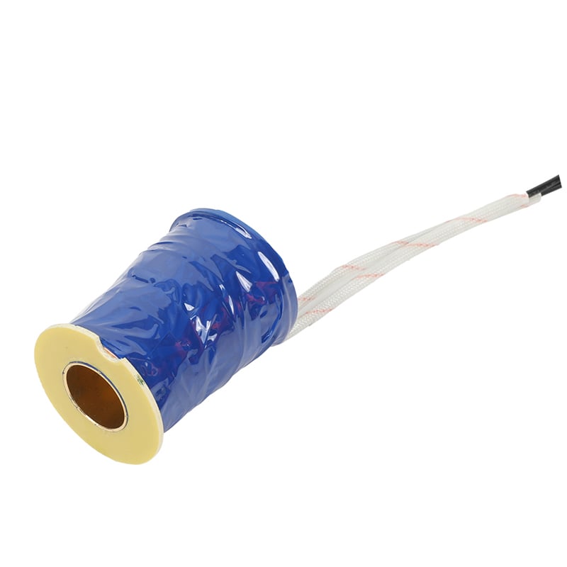
Unlike core-based inductors where the core provides mechanical support, an air core coil requires careful attention to structural integrity. Free-standing air core coil designs use self-supporting winding techniques or non-magnetic formers made from materials such as PEEK, PTFE, or other low-loss polymers. The choice of support material is critical because any material within the coil structure introduces dielectric losses that degrade Q factor.
For harsh environment applications, the air core coil may require encapsulation or conformal coating to protect against moisture, vibration, and mechanical shock. These protective measures must be implemented using low-loss, thermally stable materials that do not compromise the electrical performance advantages of the air core coil architecture. In sensor applications where the air core coil is exposed to contaminants or conductive debris, proper enclosure design prevents short circuits while maintaining the electromagnetic field access required for sensing function. The air core coil mechanical design must balance protection requirements against the need to preserve its inherent electromagnetic advantages.
The air core coil performs optimally in applications ranging from several hundred kilohertz to several gigahertz, where its high Q factor and absence of core losses provide significant advantages. While air core coil designs can function at lower frequencies, the larger physical size required to achieve sufficient inductance makes them less practical below approximately 100 kilohertz. For high-frequency RF applications, antenna matching, and resonant circuits operating above 1 megahertz, the air core coil consistently outperforms ferrite or iron core alternatives in terms of efficiency and stability.
An air core coil typically requires larger physical dimensions than an equivalent inductance ferrite or iron core inductor because air has a relative permeability of 1.0 compared to several hundred or thousand for core materials. However, this size difference becomes less significant at higher frequencies where core losses make magnetic materials less attractive. The air core coil advantage lies in its superior performance characteristics rather than size efficiency. For space-constrained applications, planar air core coil designs integrated into PCB layers can achieve competitive form factors while maintaining the electrical benefits of coreless construction.
The air core coil excels in high current applications because it cannot saturate like core-based inductors. While conductor selection and thermal management become critical considerations, the air core coil architecture maintains linear inductance regardless of current amplitude. This characteristic makes air core coil designs particularly suitable for power factor correction circuits, resonant inverters, and induction heating applications where current levels may vary widely. The absence of core saturation also eliminates the sudden inductance collapse that can cause catastrophic failure in switching power supplies using magnetic core inductors at overload conditions.
 Hot News
2026-08-24
2026-08-17
2026-08-17
2026-08-10
2026-08-03
2026-07-30
Zhongshan Landa Technology: ISO9001 & UL-certified manufacturer of custom electromagnets, push-pull solenoids, and induction coils for automation, medical, auto & appliances. Trusted global partner since 2008.
3F, Building 4, No.8 North Industrial Avenue Xiaolan, Xiaolan Town, Zhongshan, Guangdong, China
Copyright © Zhongshan Landa Technology Co., Ltd All Rights Reserved Privacy Policy

 EN
EN