 ×
×

Specifying an air core coil for low-distortion signal applications requires a systematic approach that balances electromagnetic performance, material selection, and circuit integration. An air core coil offers significant advantages over ferrite or iron-core alternatives when signal fidelity is paramount, as the absence of a magnetic core eliminates nonlinear saturation effects that typically introduce harmonic distortion. Understanding how to properly specify an air core coil ensures your signal conditioning systems, RF filters, and precision measurement equipment deliver the clean, undistorted performance your application demands.
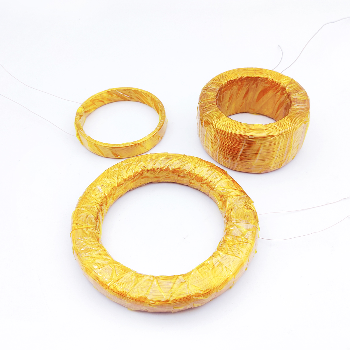
The process of selecting and specifying an air core coil for your low-distortion application involves multiple interdependent design parameters. Wire gauge, coil geometry, winding density, resonant frequency characteristics, and impedance matching all play critical roles in determining whether the finished air core coil will meet your application's stringent performance requirements. This guide walks you through each specification phase so you can communicate your needs accurately to manufacturers and validate that the air core coil you receive performs as intended.
The defining feature of an air core coil is the complete absence of ferromagnetic core material. Unlike ferrite or iron cores, which exhibit nonlinear B-H curves that generate harmonic distortion, an air core coil relies entirely on electromagnetic induction through free space. This linear relationship between current and magnetic field makes the air core coil ideal for applications where signal purity is non-negotiable. When you specify an air core coil, you immediately eliminate the risk of core saturation, which is the primary source of harmonic distortion in traditional inductor designs.
Selecting an air core coil over alternative core materials delivers measurable improvements in THD (Total Harmonic Distortion) and intermodulation performance. For audio signal conditioning, precision instrumentation, and RF filtering, an air core coil can reduce harmonic content by 15 to 40 percent compared to equivalent ferrite designs operating at similar current levels. This performance advantage makes specifying an air core coil a mandatory choice for any low-distortion signal pathway where signal integrity directly impacts system accuracy or end-user experience.
The wire used to wind an air core coil fundamentally affects both electrical performance and thermal stability. Specifying the correct wire gauge requires balancing DC resistance against skin effect losses, which become significant at higher frequencies. For a typical air core coil operating in the audio frequency range, wire gauges between 22 and 28 AWG are common, while RF applications may demand 18 to 24 AWG to minimize skin-effect resistance. When you specify an air core coil, you must also consider copper purity, as high-conductivity copper reduces DC resistance and improves Q factor.
Insulation type on the wire also influences the overall dimensions and thermal characteristics of your air core coil. Polyimide or polyurethane-coated wire provides excellent temperature stability and mechanical durability, making these materials the default choice when specifying an air core coil for industrial or automotive applications. The specified wire gauge directly determines the packing density within the coil form, which in turn affects the inductance-per-turn and the distributed capacitance of the air core coil, both critical parameters for low-distortion performance.
Winding configuration—single layer, multi-layer, or bifilar—defines the spatial distribution of turns in your air core coil and directly impacts the self-resonant frequency (SRF) and distributed capacitance. A single-layer air core coil minimizes distributed capacitance, making it the preferred choice for RF and high-frequency low-distortion applications. When you specify an air core coil, controlling the pitch (spacing between adjacent turns) becomes essential; tightly wound designs increase capacitive coupling between turns, raising the SRF and potentially introducing resonance artifacts that degrade signal purity.
For audio and baseband signal applications, a loosely wound air core coil with consistent pitch provides the most predictable performance. Specifying your air core coil with a pitch of 1.5 to 2.5 times the wire diameter typically yields excellent results, as this spacing minimizes distributed capacitance while maintaining mechanical stability. The overall aspect ratio—diameter-to-length ratio—also influences the magnetic field distribution around an air core coil; shorter, wider coils exhibit different inductance gradients than tall, narrow designs. Detailed geometry specification ensures the air core coil behaves predictably when integrated into your circuit.
The coil form onto which wire is wound for an air core coil must provide mechanical support without introducing magnetic or conductive losses. Common materials for an air core coil form include FR4 fiberglass-epoxy, phenolic resin, and PTFE (Teflon), each offering different thermal and dimensional stability characteristics. When specifying an air core coil, material selection directly affects temperature coefficient, creep resistance, and long-term dimensional stability. Fiberglass forms suit industrial applications, while PTFE excels in precision laboratory instruments where dimensional accuracy is critical.
The form must be specified with tight tolerances to ensure consistent inductance from unit to unit when manufacturing multiple instances of your air core coil design. Form diameter, thickness, and bore diameter all influence the final inductance value and the self-resonant frequency of the air core coil. When you specify an air core coil, requesting tolerance specifications for both the form and the winding ensures reproducibility. Many manufacturers offer custom forms designed specifically to optimize the air core coil for your target frequency band and impedance requirements.
The inductance value of an air core coil is determined by Faraday's law and depends on the number of turns, wire diameter, coil diameter, and winding length. When you specify an air core coil, the inductance target should be chosen to optimize impedance matching at your intended operating frequency. For a given inductance value, an air core coil always exhibits lower Q factor than its ferrite-core counterpart, which means you must account for higher resistive losses when sizing the air core coil for impedance-matching networks or filtering stages.
Frequency response of an air core coil is primarily determined by its self-resonant frequency (SRF), which is the frequency at which distributed capacitance resonates with the inductance. When specifying an air core coil, you should request that the SRF be positioned at least one full octave above your highest operating frequency to ensure stable, linear behavior across your signal bandwidth. For audio applications (20 Hz to 20 kHz), an air core coil SRF should exceed 100 kHz; for RF applications, an air core coil might require an SRF in the gigahertz range. Detailed frequency response measurement data should accompany your air core coil specification.
The DC resistance of an air core coil determines power dissipation and the insertion loss in series-coupled circuits. When specifying an air core coil, DC resistance is calculated from the total wire length, wire diameter, and copper resistivity; however, skin-effect losses at operating frequency may increase the effective AC resistance by 10 to 30 percent depending on frequency and wire gauge. Specifying an air core coil for high-current applications requires careful wire gauge selection and potentially multiple-strand wire (Litz wire) to manage AC losses and heat dissipation.
Thermal stability of an air core coil is governed by the temperature coefficient of copper and the coil form material. When you specify an air core coil, requesting a temperature coefficient specification helps you predict inductance drift over the operating temperature range. For precision applications, an air core coil with a temperature coefficient below 50 ppm/°C is desirable. Thermally-induced inductance shifts can introduce frequency-dependent distortion in signal conditioning circuits, so thermal specification is as critical as DC resistance when defining an air core coil's low-distortion performance envelope.
An air core coil eliminates the nonlinear B-H saturation curve inherent to ferromagnetic materials, which is the primary source of harmonic distortion in signal processing. Ferrite and iron cores exhibit permeability that changes with applied magnetic field strength, generating harmonic and intermodulation products that corrupt signal fidelity. An air core coil maintains strictly linear inductance across a much wider current range, making it the only choice when distortion must be minimized below 0.5 percent THD or when intermodulation performance is critical for multi-tone signal environments.
Inductance value depends on your circuit impedance target and operating frequency. For impedance matching networks, use the formula Z = ωL, where ω = 2πf and Z is your target impedance. For filtering applications, resonant frequency is determined by f = 1/(2π√LC), so you can solve for the required air core coil inductance once you know your capacitor value and target frequency. Always specify the air core coil inductance with measurement frequency noted (typically 1 kHz for audio, 100 kHz for RF) to avoid confusion, since inductance varies slightly with frequency due to distributed capacitance effects.
For audio and baseband applications, an inductance tolerance of ±5 to ±10 percent is typical and achievable through careful winding control. RF and precision measurement applications often demand tighter tolerances of ±2 to ±5 percent, which requires premium winding equipment and hand-tuning. When specifying an air core coil, request both inductance tolerance and SRF tolerance specifications; SRF tolerance directly impacts harmonic distortion performance, so specifying SRF within ±5 percent ensures predictable low-distortion behavior across your application's operating range. Custom tuning to exact specifications is available for high-volume production runs or mission-critical applications.
 Hot News
2026-09-21
2026-09-11
2026-09-08
2026-09-04
2026-09-01
2026-08-24
Zhongshan Landa Technology: ISO9001 & UL-certified manufacturer of custom electromagnets, push-pull solenoids, and induction coils for automation, medical, auto & appliances. Trusted global partner since 2008.
3F, Building 4, No.8 North Industrial Avenue Xiaolan, Xiaolan Town, Zhongshan, Guangdong, China
Copyright © Zhongshan Landa Technology Co., Ltd All Rights Reserved Privacy Policy

 EN
EN