 ×
×

Most engineers and procurement specialists rely heavily on specification sheets when selecting induction coils for electromagnetic applications. However, coil geometry—the physical dimensions, wire arrangement, spacing, and winding patterns—represents one of the most underappreciated performance drivers in electromagnetic systems. While ratings and certifications provide a baseline, the actual geometric configuration of induction coils directly determines how efficiently energy transfers, how heat distributes, and how reliably the system performs under real-world operating conditions.
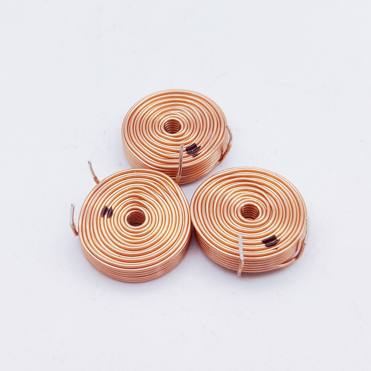
The geometry of induction coils influences magnetic field distribution, resistance characteristics, mechanical strength, and thermal behavior in ways that standard specifications often obscure. Two induction coils with identical wire gauge, turn count, and nominal inductance values can exhibit dramatically different performance profiles depending on their physical layout. Understanding these geometric nuances allows engineers to optimize system design, reduce failure rates, and improve energy efficiency across heating, power transfer, sensing, and control applications.
The spatial arrangement of wire within induction coils fundamentally reshapes the magnetic field produced and the coupling efficiency between the coil and its target load. When wire layers are wound tightly with minimal spacing, the magnetic field becomes more concentrated along the coil axis, creating stronger focal points but potentially creating dead zones at the coil edges. Conversely, induction coils with deliberately increased spacing between turns allow the magnetic field to spread more uniformly across a wider region, which benefits applications requiring broad, even energy distribution such as induction heating or wireless power transfer.
The layer configuration—whether a single-layer helix, multi-layer solenoid, or nested design—directly affects how the magnetic field superimposes. Multiple layers of induction coils can either reinforce the field (when layers are aligned) or partially cancel it (when layer windings oppose each other). Engineers designing induction coils must carefully select layer count, pitch angle, and wire diameter to achieve the desired field pattern for their specific application, whether that requires deep penetration into a workpiece or precise localization at a sensor position.
The relationship between a coil's axial length and its diameter fundamentally governs how concentrated or dispersed the magnetic field becomes. Short, wide induction coils produce fields that spread radially and fall off quickly along the axis, while long, narrow induction coils create stronger axial fields with tighter focus. This geometric ratio directly influences how efficiently induction coils couple to a target workpiece, heating element, or secondary coil. In transformer applications, for example, the aspect ratio of induction coils determines coupling coefficient and leakage inductance—parameters that specs alone cannot fully capture because they result from physical geometry rather than material properties alone.
Even when induction coils carry the same total current, the geometric arrangement of wire directly determines how that current distributes across the cross-section and how heat generates locally. In single-layer induction coils, current flows uniformly through each turn, but multi-layer designs introduce skin effect and proximity effects where current crowds toward the outer layers, especially at higher frequencies. This uneven current distribution means that certain regions of induction coils heat rapidly while others remain cool—a geometric phenomenon that specification sheets rarely address explicitly.
The pitch of the wire spiral—the axial distance advanced by each turn—also shapes thermal behavior. Tightly pitched induction coils trap heat between adjacent turns, reducing effective cooling surface area and raising internal temperatures. Loosely spaced induction coils allow air or liquid cooling medium to circulate more freely between turns, enabling higher power handling. For water-cooled induction coils, the geometric spacing becomes critical because the cooling fluid must access the entire outer surface; poor geometry results in thermal stratification where some turns operate near their maximum rating while others remain underutilized.
The choice between solid copper wire, stranded copper conductor, and specialty wire geometries introduces another layer of complexity in how induction coils manage heat. Solid copper wire concentrates heat along its centerline, while stranded or Litz wire distributes heat more evenly across multiple filaments. For high-frequency AC applications, induction coils wound from Litz wire exhibit superior thermal behavior because individual strands carry lower currents and generate proportionally less localized heat. However, this geometric benefit only manifests in specific frequency ranges; at lower frequencies, the same Litz wire configuration may underperform compared to solid copper because of higher DC resistance introduced by strand insulation.
The mechanical design of induction coils determines how well they withstand vibration, thermal expansion, and electromagnetic forces during operation. When AC current flows through induction coils, adjacent parallel wires experience attractive or repulsive forces depending on current direction. Tightly wound, rigidly supported induction coils resist these forces better than loosely wound designs, but the supporting structure itself introduces stress concentrations. An optimal geometric design balances wire support density with sufficient structural compliance to accommodate thermal expansion without cracking the wire insulation or the support material itself.
The wire diameter within induction coils also affects mechanical reliability because thinner wire is more vulnerable to fatigue from repeated thermal cycling. Thicker wire in induction coils handles mechanical stress better but increases DC resistance and heat generation per unit length. The geometric trade-off between wire gauge, support density, and turn count determines how reliably induction coils survive thousands of thermal expansion cycles in demanding industrial environments such as induction furnaces or high-power RF amplifiers.
The insulation system surrounding individual wire strands and the overall coil assembly introduces geometric constraints that directly affect reliability. Thin insulation allows more compact induction coils but provides less protection against insulation breakdown under high voltage stress. Thick insulation improves dielectric strength but reduces the number of turns that fit within a given volume, lowering inductance and increasing AC resistance. For high-voltage induction coils, the geometric arrangement of insulation layers—whether applied directly to the wire, wrapped around wire bundles, or built into a supporting form—critically determines the maximum operating voltage and long-term reliability of the coil assembly.
When selecting or designing induction coils, engineers should request detailed geometric documentation beyond standard specifications. The actual winding pattern, layer count, pitch angle, wire diameter, insulation thickness, and support structure all merit careful evaluation against the application's thermal, mechanical, and electromagnetic requirements. Induction coils designed for peak efficiency in a laboratory test bench may fail prematurely in a vibrating industrial environment if the geometric design does not account for mechanical stress. Conversely, heavily reinforced induction coils might achieve excellent reliability but sacrifice efficiency or frequency response if geometric compromises were made for structural reasons.
Custom induction coils offer the opportunity to optimize geometric parameters for the specific use case rather than accepting the compromises built into standard catalog designs. This optimization process requires close collaboration between the coil manufacturer and the application engineer to define geometric specifications that directly support the operational goals—whether those goals prioritize efficiency, thermal capacity, mechanical durability, frequency response, or coupling coefficient.
Specification sheets for induction coils focus on electrical parameters like inductance, resistance, and frequency range because these are standardized, measurable, and directly comparable across manufacturers. Geometric details such as pitch angle, layer configuration, and support structure vary widely even among functionally similar coils, making universal specifications difficult. Additionally, detailed geometric information requires technical drawings and custom documentation that standard specifications do not accommodate. Engineers working with induction coils should request full technical drawings when precision performance is critical.
At low frequencies, the geometry of induction coils has minimal impact on performance because skin effect and distributed capacitance effects remain negligible. However, as frequency increases, the geometric layout becomes critical because current concentrates toward the outer surface of conductors and distributed capacitance between turns creates frequency-dependent effects. Induction coils designed for low-frequency applications (50–60 Hz) can tolerate looser winding patterns, while those operating at kilohertz or megahertz ranges require tight geometric control to manage skin effect and minimize parasitic capacitance.
Absolutely. Two induction coils with identical nominal inductance, resistance, and DC ratings can exhibit markedly different performance if their geometric designs differ. Factors such as wire arrangement, layer configuration, support material, and thermal management geometry directly influence how induction coils behave under sustained current, thermal cycling, vibration, and frequency variation. This is why many experienced engineers insist on detailed geometric documentation and even sample testing before committing large production orders for induction coils in mission-critical applications.
 Hot News
2026-09-21
2026-09-11
2026-09-08
2026-09-04
2026-09-01
2026-08-24
Zhongshan Landa Technology: ISO9001 & UL-certified manufacturer of custom electromagnets, push-pull solenoids, and induction coils for automation, medical, auto & appliances. Trusted global partner since 2008.
3F, Building 4, No.8 North Industrial Avenue Xiaolan, Xiaolan Town, Zhongshan, Guangdong, China
Copyright © Zhongshan Landa Technology Co., Ltd All Rights Reserved Privacy Policy

 EN
EN