 ×
×

Selecting the right push pull solenoid for OEM applications requires understanding critical performance specifications, operational constraints, and long-term reliability factors. This buying guide addresses the essential decision criteria OEM manufacturers face when integrating push pull solenoid technology into automated systems, medical devices, industrial controls, and consumer electronics. Whether you're designing a new product line or upgrading existing equipment, the push pull solenoid you choose directly impacts cycle life, energy efficiency, and manufacturing costs.
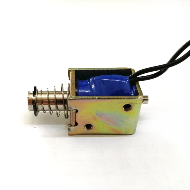
OEM manufacturers must evaluate push pull solenoid options against application-specific requirements including stroke length, force output, duty cycle, and environmental operating conditions. A push pull solenoid operates through electromagnetic force generation, converting electrical energy into linear mechanical motion in both directions. Unlike single-acting solenoids that rely on spring return mechanisms, a push pull solenoid provides active force in both extension and retraction phases, offering precise bidirectional control essential for automated positioning, locking mechanisms, and valve actuation systems.
The stroke length of a push pull solenoid determines the linear travel distance the plunger can achieve during activation. OEM applications typically require stroke lengths ranging from 3mm to 50mm, with each push pull solenoid design optimized for specific travel ranges. Shorter stroke push pull solenoid models deliver higher force density, while longer stroke configurations trade peak force for extended reach. When specifying a push pull solenoid, calculate the minimum force required at the end of stroke, as electromagnetic force decreases non-linearly with plunger displacement. A push pull solenoid rated at 20N holding force may deliver only 12N at maximum stroke extension, making initial force curves critical for reliable operation.
Push pull solenoid models are available in standard DC voltage ratings including 12V, 24V, and 48V configurations. The voltage selection for your push pull solenoid directly affects coil resistance, current draw, and heat generation. A 12V push pull solenoid typically draws higher current than an equivalent 24V push pull solenoid to achieve comparable force output, resulting in greater resistive heating. For battery-powered or energy-sensitive OEM applications, selecting a higher voltage push pull solenoid reduces wiring losses and improves overall system efficiency. Calculate total power consumption across the expected duty cycle, as continuous operation of a push pull solenoid designed for intermittent use leads to thermal failure.
Every push pull solenoid carries a maximum duty cycle rating expressed as a percentage of on-time versus total cycle time. An intermittent-duty push pull solenoid rated at 10% duty cycle can operate for 10 seconds within every 100-second period without exceeding thermal limits. Continuous-duty push pull solenoid models incorporate enhanced coil designs and heat dissipation structures to sustain 100% duty cycles, but at higher cost and larger package sizes. OEM manufacturers must match push pull solenoid thermal characteristics to actual application demand cycles. Installing a standard push pull solenoid in a continuous-operation application causes coil insulation degradation, resistance drift, and eventual open-circuit failure.
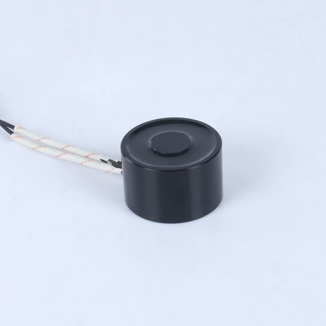
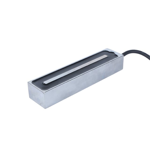
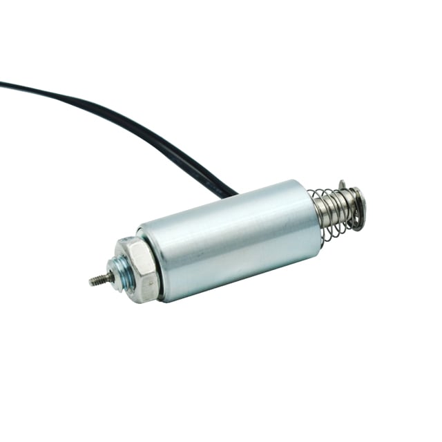
Push pull solenoid mounting options include flange mount, threaded body, and bracket configurations, each offering different installation advantages. A flange-mount push pull solenoid provides secure perpendicular installation to mounting surfaces with bolt-through holes, ideal for panel-mount applications. Threaded-body push pull solenoid designs allow direct installation into tapped holes, reducing assembly complexity in compact OEM products. The mechanical interface between the push pull solenoid plunger and driven load requires attention to axial alignment, as lateral forces reduce operational life and increase friction losses. Use flexible couplings or clevis joints when connecting a push pull solenoid to mechanisms with potential misalignment.
Operating environment significantly impacts push pull solenoid reliability and service life. Standard open-frame push pull solenoid designs suit controlled indoor environments but fail rapidly when exposed to moisture, dust, or corrosive atmospheres. Sealed push pull solenoid configurations with potted coils and environmental gaskets provide IP65 or IP67 protection levels suitable for outdoor, washdown, or harsh industrial applications. Temperature rating is equally critical, as a push pull solenoid designed for 0°C to 40°C ambient operation exhibits force degradation and potential failure at -20°C or 60°C extremes. For automotive or outdoor OEM applications, specify a push pull solenoid with extended temperature range ratings and verify performance curves across the expected thermal envelope.
Push pull solenoid electrical terminations include wire leads, spade terminals, and quick-connect options. Wire-lead push pull solenoid models offer installation flexibility but require secure strain relief to prevent conductor fatigue at the coil junction. When integrating a push pull solenoid into electronic control systems, consider back-EMF suppression through flyback diodes or snubber circuits, as inductive kickback from rapid de-energization can damage solid-state drivers. A PWM-driven push pull solenoid enables force modulation and reduced holding current, extending thermal capacity and enabling soft-start operation that reduces mechanical shock loads on driven mechanisms.
OEM manufacturers benefit from push pull solenoid suppliers offering engineering support for application-specific modifications. Standard catalog push pull solenoid products serve many applications, but optimized designs may require custom stroke lengths, non-standard voltage ratings, or specialized plunger tip configurations. Evaluate whether a push pull solenoid supplier provides force-displacement curve data, thermal rise test results, and cycle life validation across your specific operating conditions. A push pull solenoid supplier with in-house design capability can adapt coil winding configurations, magnetic circuit geometry, and materials selection to achieve performance targets unavailable in off-the-shelf push pull solenoid products.
Demand third-party testing documentation or in-house validation data demonstrating push pull solenoid performance under realistic load conditions. Cycle life testing should reflect actual duty cycles, force loading, and environmental conditions your push pull solenoid will encounter in service. A push pull solenoid validated to one million cycles at 50% duty cycle and 25°C ambient may fail at 100,000 cycles under continuous operation at 50°C. Request accelerated life test data showing force consistency, current stability, and mechanical wear patterns across the expected product lifetime. Quality push pull solenoid manufacturers provide statistical process control data demonstrating manufacturing consistency across production batches.
While unit price drives initial push pull solenoid selection, total cost of ownership includes failure rates, warranty claims, and field service expenses. A lower-cost push pull solenoid with marginal thermal design may generate higher long-term costs through increased failure rates and customer satisfaction issues. Evaluate push pull solenoid suppliers based on supply chain stability, lead time consistency, and inventory flexibility supporting your production schedule. Dual-source your push pull solenoid components when feasible, ensuring design compatibility across suppliers to mitigate supply disruption risks. Document push pull solenoid specifications in detail including dimensional tolerances, electrical parameters, and performance acceptance criteria to enable supplier qualification and alternate sourcing without design iteration.
A push pull solenoid designed for intermittent duty typically achieves 500,000 to 2,000,000 mechanical cycles depending on force loading, duty cycle, and operating temperature. Continuous-duty push pull solenoid models with enhanced thermal design can exceed 5,000,000 cycles when operated within rated specifications. Actual push pull solenoid lifespan depends on maintaining proper alignment, avoiding over-voltage conditions, and operating within thermal limits. Accelerated life testing under application-representative conditions provides the most reliable push pull solenoid lifespan prediction for your specific OEM product.
Calculate push pull solenoid force requirements by summing all resistive forces including friction, spring preload, and inertial loads during acceleration. Add a safety margin of 25% to 50% to account for force degradation over the push pull solenoid stroke length and manufacturing tolerances. Review the push pull solenoid force-displacement curve from your supplier to verify available force at the required stroke position. Dynamic applications requiring rapid actuation need higher peak force from the push pull solenoid to overcome inertial loads, while static holding applications can use lower-force push pull solenoid models with reduced power consumption.
Operating a push pull solenoid at voltages exceeding the rated value increases current, force output, and heat generation, potentially causing immediate coil damage or reduced operational life. Under-voltage operation of a push pull solenoid reduces force output and may prevent full stroke completion, causing mechanical binding or incomplete actuation. Some push pull solenoid applications intentionally use reduced holding voltage after initial pull-in to lower power consumption, but this requires electronic control and verification that reduced-voltage force maintains the required load. Always consult push pull solenoid manufacturer specifications before operating outside rated voltage ranges, as warranty coverage typically excludes over-voltage failures.
 Hot News
2026-06-26
2026-06-23
2026-06-19
2026-06-17
2026-06-15
2026-06-12
Zhongshan Landa Technology: ISO9001 & UL-certified manufacturer of custom electromagnets, push-pull solenoids, and induction coils for automation, medical, auto & appliances. Trusted global partner since 2008.
3F, Building 4, No.8 North Industrial Avenue Xiaolan, Xiaolan Town, Zhongshan, Guangdong, China
Copyright © Zhongshan Landa Technology Co., Ltd All Rights Reserved Privacy Policy